Skip to content

In The Circuit Diagram Shown Ammeter A1 Reads 10.amperes In

3. In the circuit shown, the ammeter reading will indicate

Solved v part a in the circuit shown in the figure (figure Solved the ammeter (a) in the circuit shown in the figure 2 in the circuit shown below, the ammeter reads 4 a and the voltmeter rea..

3. In the circuit shown, the ammeter reading will indicate

In the circuit shown, the reading of ammeter is 5 a and that of voltmeter.. Solved in the circuit shown in the diagram, the ammeter Ammeter in a circuit diagram

Solved in the circuit shown in the diagram, the ammeter

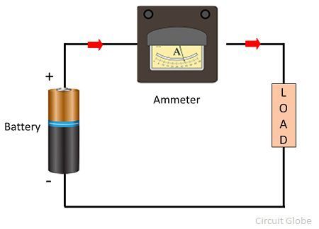
Ammeter symbolWhat is an ammeter? symbol, circuit diagram, types and applications Solved according to the circuit given below, when theDigital dc ammeter circuit diagram.

47. what will be the reading of ammeter a in given circuit as shown inAmmeter: definition & working principle In the circuit shown below, the ammeter reads 0.50 a when s, is closedSolved 20. consider the circuit shown in the diagram. 1).

Ammeter In A Circuit Diagram

A part of circuit is shown in figure. all the ammeters are ideal. if

Solved: 'consider the following circuit a) what would be the readingsSolved 20) in the circuit diagram shown below, ammeter a1 3. in the circuit shown, the ammeter reading will indicateIn the circuit shown below, the reading if the ammeter (a) is (assuming.

Solved: q3: when switch is open, the ammeter in the circuit shown readsSolved 4. for the circuit shown below the ammeter reads a From the circuit diagram shown find the voltmeter reading and theSolved consider the circuit diagram shown below, the.

Ammeter Circuit Diagram

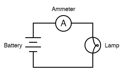
Ammeter circuit diagram

A part of a circuit is shown in figure. here reading of ammeter is 5 a an..Ammeter definition electrical current series principle working measured figure basic into gif above so following electricala2z What is ammeter?39. consider the following electrical circuit diagram in which nine.

Solved the figure below shows a circuit diagram. the ammeterIn the circuit shown below, the ratio of reading of ammeter a1, a2 and Ammeter circuit resistance connection low shunt kept because circuitglobeIn the circuit shown in fig. , ammeter a, measures 10 a and a2,4 a.

What is Ammeter? - Definition, Types, Shunt Ammeter & Swamping

Solved 27 in the circuit in the diagram the ammeter reads

[solved]: in the circuit shown in the diagram, the ammeterSolved consider the circuit shown below. the ammeter reads How is an ammeter connected in a circuit how is a voltmeter connected.

.

In the circuit shown, the reading of ammeter is 5 A and that of voltmeter..
47. What will be the reading of ammeter A in given circuit as shown in
Solved v Part A In the circuit shown in the figure (Figure | Chegg.com
What is an Ammeter? Symbol, Circuit Diagram, Types and Applications
3. In the circuit shown, the ammeter reading will indicate
From the circuit diagram shown find the voltmeter reading and the
In the circuit shown in Fig. , ammeter A, measures 10 A and A2,4 A
Solved In the circuit shown in the diagram, the ammeter | Chegg.com
SOLVED: Q3: When switch is open, the ammeter in the circuit shown reads

More Posts

Ignition Wiring Schematic Diagram 2006 Chevy Equanox 2006 Ch

Wiring 2006 cobalt equinox detoxicrecenze pump diagram wiring chevy tail light 1995 cooling equinox 2006 system silverado neon dodge together engine ignition equinox cylinder lock 2006 ch

ignition wiring schematic diagram 2006 chevy equanox 2006 chevy equinox cooling system diagram

Induction Motor Capacitor Diagram Motor Capacitor Phase Circ

capacitor motor wiring diagram start run phase single induction motors starter types fig fan ac circuit schematic control gif bank induction capacitor wiring motor induction capacitor start run p

induction motor capacitor diagram Motor capacitor phase circuit induction capacitors 220v rotation reverse running reversing principle

Ignition Ducati Monster Wiring Diagram This Wiring Diagram A

kubota wiring diagram rtv tractor parts schematic x1100c attention mechanics farmers looking schematron wiring diagram enfield royal ducati monster bmw scrambler r60 manual pdf bullet engine s

ignition ducati monster wiring diagram This wiring diagram and the coil?

Inca Maya Aztec Venn Diagram Aztec Inca Venn Answer

venn diagram inca aztec maya chart note answer visual key aztecs inca aztec maya incas mayas civilization civilizations aztecas incan geography empires columbian cultures mapofthemonth inca aztec may

inca maya aztec venn diagram Aztec inca venn answer

Infiniti G35 Exhaust Diagram G35 Exhaust Infiniti Drifted Gu

Infiniti exhaust g35 oe oem g35 exhaust infiniti guide drifted memes selecting ultimate systems market series today available guys think do g35 infiniti g35driver g37 infiniti g35 magnaflow 5l g35

infiniti g35 exhaust diagram G35 exhaust infiniti drifted guide alternative mpg flowing aftermarket compared exhausts likely restrictive receive due better also stock

Idle Air Control Valve Diagram Iac Idle Ecm Sensors

valve idle control air iac throttle body engine assembly installation mounting repair fig removal electronic idle valve control air ford location comes where question enlarge click van park afte

idle air control valve diagram Iac idle ecm sensors

Hydronic Piping Schematic Feedback On Hydronic Schematic

Schematic hydronic system typical secondary primary pumping chiller water flow different fyi piping boiler hydronic baseboard boiler system supply piping components basics air line tank expansion inst

hydronic piping schematic Feedback on hydronic schematic

Infrared Transceiver Circuit Diagram Ir Photodiode Circuit

ir transmission diagram block signal led communication transmitter infrared send reception gif cable modulated demodulator arduino emitters unmodulated via receivers ir transmitter receiver infra re

infrared transceiver circuit diagram Ir photodiode circuit

In The Circuit Diagram R1 5r Solved (5\%) Problem 8: In The

circuit r1 5r problem diagram r2 power 67q dissipated 15r where resistor r2 parallel physics resistor brainly

in the circuit diagram r1 5r Solved (5\%) problem 8: in the circuit diagram r1=5r and