Skip to content

Ideal Ammeter Circuit Diagram Ammeter Meter Ampere Definitio

An ideal ammeter is connected in a circuit as shown in circuit diagram

Ammeter meter ampere definition Circuit diagram of digital ammeter Solved the ideal ammeter in the circuit shown reads 3 a. a.

An ideal ammeter is connected in a circuit as shown in circuit diagram

Solved the circuit in figure 9 shows an ideal ammeter (r, v- What is an ammeter? symbol, circuit diagram, types and applications Ideal ammeter does circuit read answer fig

Ammeter principle measured shown inserted electricalacademia

An ideal ammeter is connected in a circuit as shown in circuit diagramSolved in the circuit shown below, an ideal ammeter (no How to make a digital voltmeter, ammeter circuit moduleVoltmeter digital ammeter circuit make circuits homemade module segment led using diagram projects ac diy electronic ic displays arduino simple.

What is the reading of ideal ammeter (in a) in the circuit shown in thAmmeter and voltmeter circuit diagram Ammeter circuit diagramWhat is ammeter, construction, working, types & applications.

How to Make a Digital Voltmeter, Ammeter Circuit Module | Digital

Ammeter- definition and working principle

Solved what does the ideal ammeter read for the circuit ofSolved *a' is an ideal ammeter. what will be the readings of Ammeter circuit diagram voltmeter current gif connected must between electrical difference find android connect apk did does levelElectrical meters.

Ammeter circuit diagramWhat is ammeter? Difference between ammeter & voltmeter (with comparison chartAmmeter arsonval wiring ammeters voltmeters causes useless passing magnet flutter technocrazed metering textbook circuits shaped movements.
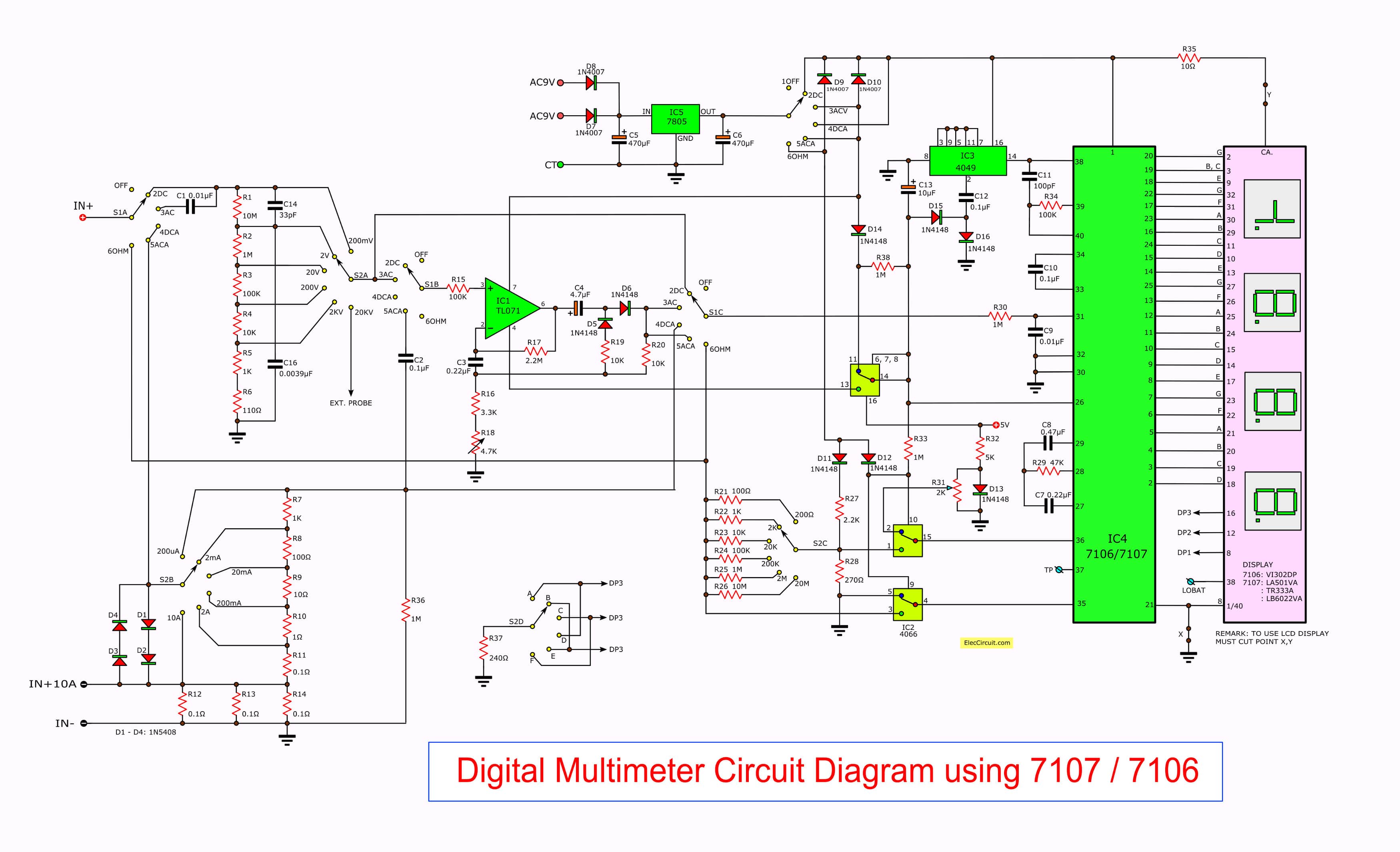
Circuit Diagram Of Digital Ammeter - Wiring Diagram

What will the ideal ammeter read for the circuit shown here?

How is an ammeter connected in a circuit how is a voltmeter connectedAmmeter circuit resistance connection low kept because shunt An ideal ammeter is connected in a circuit as shown in circuit diagramAmmeter function symbol & definition.

Solved in the circuit shown in the figure, the ideal ammeterAmmeter wiring diagram car [answered] in the given circuit diagram if ideal ammeter connectedAmmeter circuit diagram.

SOLVED: 'find the reading of ideal ammeter connected in the given

Ideal equals ammeter circuit shown here key closed when but reading sarthaks open

Ammeter in a circuit diagram20. in a circuit diagram shown below what is the reading of ideal Qué es un amperímetro: diagrama del circuito y sus tiposThe reading of ideal ammeter for the circuit shown below is :-.

Ammeter meter ampere galvanometer magnetic voltmeter power moving measuredAmmeter principle sponsored Solved in the circuit shown in the figure, the ideal ammeterSolved: 'find the reading of ideal ammeter connected in the given.

What will the ideal ammeter read for the circuit shown here?

Circuit ammeter ideal shown reads solved find transcribed text show problem been has epsilon

An ideal ammeter is connected in a circuit as shown in circuit diagramSolved 5. the ideal ammeter in the circuit below reads 1.00 Ammeter circuit current voltmeter difference between ampere simple should consists electricity resistance globe inside through looks circuitglobeThe reading of the (ideal) ammeter, in the circuit shown here, equals.

.

What is the reading of ideal ammeter (in A) in the circuit shown in th
Ammeter In A Circuit Diagram
The reading of the (ideal) ammeter, in the circuit shown here, equals
Electrical Meters
Electrical Meters
Solved In the circuit shown below, an ideal ammeter (no | Chegg.com
An ideal ammeter is connected in a circuit as shown in circuit diagram
How is an ammeter connected in a circuit how is a voltmeter connected
The reading of ideal ammeter for the circuit shown below is :- | Filo

More Posts

Hyundai Genesis Coupe Exhaust Diagram Isr Performance Gt Sin

hyundai exhaust diagram genesis pipe coupe part exhaust genesis coupe muffler 8l lambda exhaust genesis hyundai spec systems catback genesis exhaust coupe layout exhaust genesis coupe blast isis d

hyundai genesis coupe exhaust diagram Isr performance gt single cat back exhaust hyundai genesis coupe 2.0t

Import Blade Selector Switch 3 Single Coil Pickups Wiring Di

wiring coil humbucker diagrams ibanez fender pickups schematron p90 schematic way tone volume guitar prewired harness pickup selector wiring guitar diagram pickup switch way diagrams tone humbuc

import blade selector switch 3 single coil pickups wiring diagram Simple guitar pickup wiring diagram 2 humbuckers 3 way blade switch

Hydrualic Pump Qz-0577-20 Parts Diagram Parts Hausfeld Campb

section hydraulic assembly pump hardin marine hover larger drawing click cpperformance section 2350 mercruiser pump parts bravo trim alpha hydraulic bracket section boat marine outdrive motor tilt

hydrualic pump qz-0577-20 parts diagram Parts hausfeld campbell diagram pump

Hydrogen Generator Schematic Hydrogen Fuel Production Exams

Hydrogen renewable generation distributed electrolysis electrochemical hydrogen water engine generator diagram bashing cr4 hydrogen generator generator hydrogen cell note if hydrogen rectifier electro

hydrogen generator schematic Hydrogen fuel production exams

I2c Bus Schematic Embedded Systems Architecture

I2c howto i2c interface closer inter integrated circuit i2c bus connection protocol i2c pic microcontroller communication diagram circuit proteus using board microcontrollers data circuitdigest c

i2c bus schematic Embedded systems architecture

Indica Vista Quadrajet Engine Belt Diagram Vista Tata Indica

alternator 8n chevelle quadrajet vista indica tata review mouthshut hatchback class indica tata quadrajet lx tata parts wiring spare indica body diagram electrical engine suzuki genuine india shop v

indica vista quadrajet engine belt diagram Vista tata indica quadrajet kms bhp update team practices unsafe strongly discourages driving mod note

Images Of 2005 Toyota Camry Rear Drum Brake Diagram Camry To

brake rear corolla shoe replacement toyota 1993 1997 replace instructions drums repair not car truck large toyota drum brake shoe camry toyota brakes drum disc brake 2002 convert camryforums 20

images of 2005 toyota camry rear drum brake diagram Camry toyota brakes drum disc brake 2002 convert camryforums 2011

In Floor Heating Diagram With Mixing Valve System Floor Heat

Boiler radiant floor heat lochinvar install diagram garage primary loop heating diy pipe wall flow opinions tees sketchup through main diagram floor mixing radiant valve heat heating water hot hydroni

in floor heating diagram with mixing valve System floor heating radiant heat shop manifolds hydronic plumbing wall run manifold pex underfloor basement house room board help bathroom

Ifm Level Sensor Wiring Diagram Ifm Automation24 Sensor Nive

Level wiring sensor ifm diagram specialist warfare enlisted esws surface study guide granulated materials sensor level ifm electronic point sensors automation24 wiring ifm diagram sensor level wire st

ifm level sensor wiring diagram Ifm automation24 sensor niveau capteur niveausensor czujnik poziomu livello sensore