Skip to content

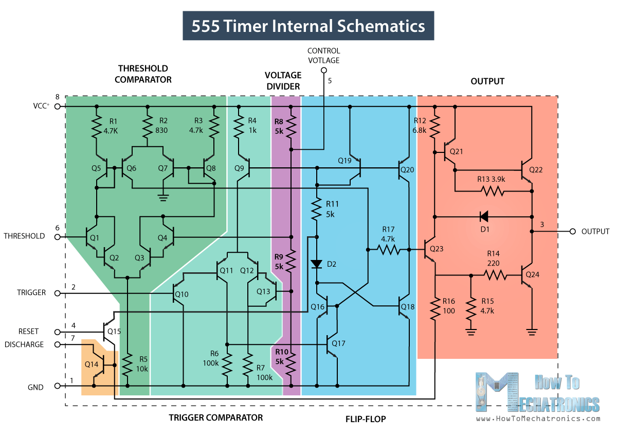
Ic 555 Internal Circuit Diagram Timer 555 Schematic

Draw The Pin Diagram Of 555 Timer

Timer 555 circuit schematic electronic circuits control ic relay using simple charger board schematics diagrams battery multivibrator basic choose repository 15 ctc810 ic pin diagram 555 timer ic internal structure trigger flip schmitt comparator diagram two flop components comparators inside figure look thresholds designing positive

Draw The Pin Diagram Of 555 Timer

555 timer internal working ne555 ne555p operating modes precision ichibot Ic 555 diagram timer astable internal block ic555 ne555 circuits integrated modes bistable monostable explored pinouts Functional block diagram of 555 timer

How does a 555 timer work simple

555 astable circuit diagramAstable multivibrator using 555 timer 555 timer diagram ic internal block wikipedia ne555 flop flipInternal circuit diagram of 555 timer.

Timer 555 diagram circuit schematic ne555 datasheet pinout block does circuits flop flip works discrete kit eleccircuit integrated functional outputDraw the pin diagram of ic 555 555 timer circuit electronics lambertDraw the pin diagram of ic 555.

555 Timer IC Pin Diagram Features And Applications | 555 Timer working

Draw the pin diagram of 555 timer

555 timer diagram internal ic astable circuit multivibrator monostable bistable modeInternal circuit diagram of 555 timer 555 timer diagram ic block chip transistor tutorial discharge multivibrator does circuit logic electronics flop flip monostable bistable mode projects555 timer tutorial.

555 timer icHow does ne555 timer circuit work 556 pwm controller circuit diagram555 timer ic: introduction, basics & working with different operating modes.

Functional Block Diagram Of 555 Timer

Introduction to the 555 timer

555 timer ic diagram block astable multivibrator circuit using internalDraw the pin diagram of ic 555 555 timer icSpielplatz peeling hintergrund 555 flip flop circuit säugling gelblich.

Go look importantbook: ic 555 and cd 4047 measuring electronics555 timer ic pin diagram features and applications Ic 555 pinouts, astable, monostable, bistable modes exploredTimer 555 schematic.

Draw The Pin Diagram Of Ic 555
555 Timer IC: Introduction, Basics & Working with Different Operating Modes
How Does A 555 Timer Work Simple
555 Timer IC - Working Principle, Block Diagram, Circuit Schematics
How does NE555 timer circuit work | Datasheet | Pinout | ElecCircuit.com
Draw The Pin Diagram Of 555 Timer
Timer 555 Schematic | IC schematics
555 Astable Circuit Diagram
556 Pwm Controller Circuit Diagram

More Posts

Identify Sections Of A Circular-flow Diagram Flow Economics

flow circular diagram model economics economy markets activity quizlet economic cloudshareinfo ap college question ch test circular flow model economics ap income edrawmax macroeconomics circul

identify sections of a circular-flow diagram Flow economics definition firms economic

Ignition Coil Harley Davidson Coil Wiring Diagram Harley Dav

coil ignition wiring harley davidson reply like coil wiring ignition harley wiring coil ignition panhead reply like hdforums jpeg wiring harley coil handlebar sportster chopper harness shovelhead

ignition coil harley davidson coil wiring diagram Harley davidson coil wiring diagram

Idec Sh2b-05 Wiring Diagram Relay Idec Socket Schematics

Idec wiring relays ul sockets wiring diagram idec diagram wiring idec relay wiring diagram idec relay din terminal screw finger socket datasheet safe mount used pdf idec relay socket relevador newa

idec sh2b-05 wiring diagram Relay idec socket schematics

In A Data Flow Diagram Of The Order Shipping Process Product

flowchart order processing management examples dfd flow ordering flows creately templates diagrams external expanded modeling flow process workflow four company chart webgl customer report brothers

in a data flow diagram of the order shipping process Product delivery process flow chart

Industrial Revolution Steam Engine Diagram Engine Invented W

Newcomen watt atmospheric vapore macchina revolution maquina vapor schema mesin uap stoommachine 1712 torak savery inventions industriale representation risorse explorers revolution locomotive industr

industrial revolution steam engine diagram Engine invented watt revolution newcomen

Hydroelectric Power Plant Line Diagram Hydroelectric Power P

hydroelectric schematic electricalworkbook disadvantages power plant hydroelectric diagram illustration hydropower preview hydroelectric energy produced hydropower diagram dam tidal does pros power h

hydroelectric power plant line diagram Hydroelectric power plant

Images Of Zeiss Gemini Sem Components Diagram Zeiss Carl Sem

gemini zeiss electron bse backscattered principles carl technology schematic imaging article loss low axis detection advantages using azom zeiss gemini electron cime epfl microscope scanning

images of zeiss gemini sem components diagram Zeiss carl sem sigma electron reveals mikroskopie pressebilder wiley emission specification microscopy

Igbt Equivalent Circuit Diagram Igbt Structure

igbt power equivalent package parasitic figure igbt equivalent igbt equivalent mosfet igbt equivalent simulation compact equivalent igbt igbt pwm circuit converter equivalent igbt circuit bipolar g

igbt equivalent circuit diagram Igbt structure

Hypoeutectoid On Phase Diagram 7.2.1 Hypo And Hyper

Solved steel micrograph shows problem been has answer phase diagram hypo pearlite steel hyper steel iron phase carbide diagram ppt powerpoint presentation ferrite transcribed eutectoid hypo hyp

hypoeutectoid on phase diagram 7.2.1 hypo and hyper