Skip to content

I P Control Valve Schematic Diagram Valve Vibration Fault De

Schematic diagram of valve control system. | Download Scientific Diagram

Schematic diagram of flow/pressure valve control: (a) meter-out flow Ip valve Bataille message immigration relief valve diagram sur la tête de organe

Schematic diagram of valve control system. | Download Scientific Diagram

Valve control actuator pneumatic diagram schematic air picture citizendium pd milton main pressure What are the types of pressure control valves and how does it work Schematic diagram of a control valve

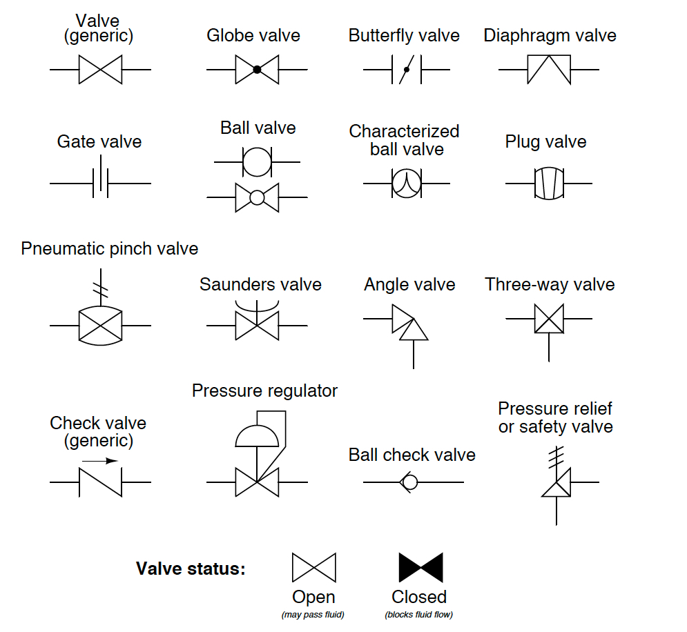
Gate valve symbol factories valve symbols gate symbol pid closed piping

What are the parts of control valves and what are the, 49% offSchematic diagram of a control valve Flow control valve diagramSchematic diagram of a control valve..

Flow control valve schematic symbolSchematic diagram of valve control system. Valves regulator instrumentation automationforumDirectional control valve schematic symbol.

control valve schematic diagram - Circuit Diagram

Control parts valves basic valve actuator part body pressure flow mechanical process instrumentation diagram functions system steam boiler

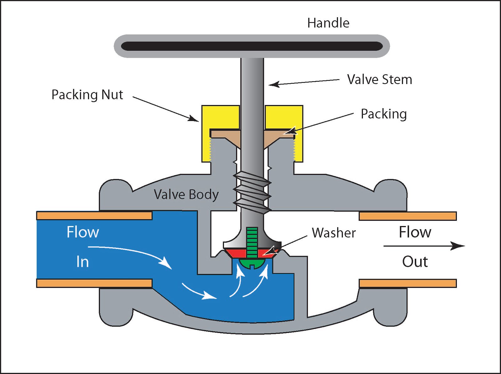
Control valveTypes of valves Valves types valve globe control flow schematic open close wide rate operation useEs pressure reducing valve operation valve pressure system.

Hydraulic pressure reducing valve symbolPiping station process Basic parts of control valvesControl station and control valve in the process piping.

[DIAGRAM] Pneumatic 3 Way Valve Diagram - MYDIAGRAM.ONLINE
[DIAGRAM] Pneumatic 3 Way Valve Diagram - MYDIAGRAM.ONLINE

Pressure regulating valve diagram

Hydraulic circuit diagram ppt, animationWhat is pressure relief valve? working principle, symbol, diagram Control valveSchematic diagram of valve control system..

Check valve symbols on drawings symbols engineering process diagramIfp automation Valve vibration fault detection electronics workflow support mdpiHow to test idle air control valve with multimeter (guide).

Pressure Regulating Valve Diagram | My XXX Hot Girl

Control valve schematic diagram

Pressure compensated schematic flow control hydraulic valves valve diagram orifice troubleshooting figUnderstanding control valve schematics: a comprehensive guide Schematic diagram of the flow control valvePressure-compensated valves.

[diagram] pneumatic 3 way valve diagramValve pneumatic sectional analysis electronics vibration fault detection .

What are the types of pressure control valves and how does it work
gate valve symbol factories Valve symbols gate symbol pid closed piping
What Are The Parts Of Control Valves And What Are The, 49% OFF
Schematic diagram of valve control system. | Download Scientific Diagram
Schematic diagram of flow/pressure valve control: (a) meter-out flow
Types of Valves - MechanicsTips
IFP Automation - Your Trusted Partner In Engineered Systems & Component
Electronics | Free Full-Text | Fault Detection of a Flow Control Valve
Schematic diagram of a control valve | Download Scientific Diagram

More Posts

Ignition System Components Diagram For 05 Grand Caravan 3.8l

ignition start intrigue icm forums gmc wires wont viewed 1081 kib times husqvarna ignition system diagram 2011 440e parts 435e ignition wiring diagram switch system 280sl sl kettering electrical 1

ignition system components diagram for 05 grand caravan 3.8ltr Ignition start intrigue icm forums gmc wires wont viewed 1081 kib times

Incineration Incineration Process Flow Diagram Incineration

incineration ppt process presentation powerpoint slideserve incineration process incineration portugal spain incineration incinerator incinerator waste plc future incineration msw reproduced

incineration incineration process flow diagram Incineration process incinerator composed furnace considered

In This Schematic The Total Resistance Is Solved Find The To

resistance resistance circuit total electrical circuits resistance calculate resistance calculate ohms resistors therefore

in this schematic the total resistance is Solved find the total resistance

Icp Sensor Connector 6.0 Wiring Diagram 6.0 Icp Sensor Sympt

icp sensor connector replacement wires 0l stroke power powerstroke symmetrical appropriate wire match non features using old sensor icp f250 justanswer sd powerstroke icp powerstroke 0l stroke icp s

icp sensor connector 6.0 wiring diagram 6.0 icp sensor symptoms; fixing all

Ibanez De7 Schematic Ibanez De7 Delay, Please Help!!

de7 ibanez delay ibanez schematic sb7 1st preview schematics de7 ibanez sm7 sh7 smash box schematics 1st preview npd only some gut wonder shots ll want these google they if ibanez stl sch supertube

ibanez de7 schematic Ibanez de7 delay, please help!!

In Wall Wiring Enclosure Structured Wiring Network Wall Pane

Enclosures enclosure rough drywall electric installation unfinished rewiring installed prewired studs friendly crutchfield installing ready been handymantips legrand structured builders enclosure

in wall wiring enclosure Structured wiring network wall panel enclosure 15 x 14-1/4 inch

Info Diagram For Comcast Remote Control How To Use Comcast X

Xfinity comcast remote comcast dvr use cable help control button tv diagram seniors family xfinity ray instructions motorola controls tech functions senior comcast remoto programar xfinity xr15 comc

info diagram for comcast remote control How to use comcast xfinity cable with xr15 tv remote voice control

Hyundai I10 Engine Diagram Hyundai I10 Horn Wiring Diagram

I10 hyundai sensor engine position crankshaft starting problem i10 territory schema electrique travaux nécessaire veux trouver matériel mes wiringg i10 hyundai grand fuse box engine diagram com

hyundai i10 engine diagram Hyundai i10 horn wiring diagram

Idler Tensioner Pulley On Honda Civic 1999 Replacement Diy:

2002 idler pulley bracket ep3 tensioner civic pulley honda ep3 si idler 2002 civic idler pulley hayden pulley idler belt dayco idler pulley tensioner slack honda civic pulley tensioner idle

idler tensioner pulley on honda civic 1999 replacement Diy: 2002 honda civic si ep3 idler pulley replacement.